Centerless Grinding of Micro Pins and Shafts: What Tolerances to Expect
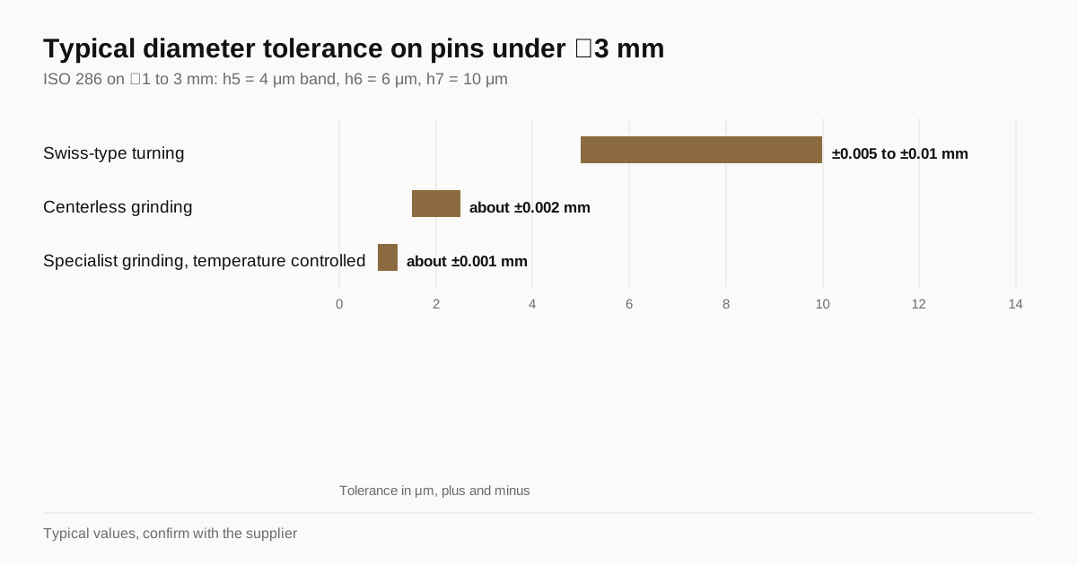
A turned micro pin is typically good to ±0.005 mm on diameter. A ground one can be good to ±0.002 mm, round to a micrometer and smooth enough to slide in a guide bush without lubricant. That difference sets the price of ejector pins, dowels, shafts, needles and the bar stock used on Swiss-type lathes. Centerless grinding is the process behind it. This guide explains how it works at micro scale and what to put on the drawing. For the turning side, see the guide to Swiss-type turning for micro parts.
How centerless grinding works
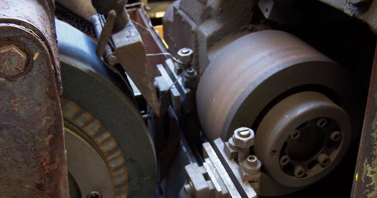
Two wheels face each other. The larger one grinds. The smaller one, called the regulating wheel, is rubber or resin bonded, turns slowly and controls how the part rotates and moves forward. The part rests on a thin work blade between them, and no center, chuck or collet holds it.
Because nothing clamps the part, there is no deflection from a holder and no marks from jaws. A slender pin is supported along its length by the blade and the wheels, and the part is ground as it passes. That makes the process well suited to long, thin shafts that would bend between centers on a cylindrical grinder.
Through-feed and in-feed
| Mode | How it works | Good for | Limit |
|---|---|---|---|
| Through-feed | Part passes straight through the wheels, tilted regulating wheel moves it forward | Plain pins, rods, shafts, bar stock | Ground diameter must be the largest diameter |
| In-feed (plunge) | Part sits against a stop, wheel moves in to grind a section | Parts with heads, shoulders, steps | Slower, shorter ground length |
| End-feed | Tapered part is fed into a tapered wheel setup | Tapered pins and needles | Special tooling |
Typical practice for orientation. Shops specialize in one or two of these.
Through-feed is the fastest and the cheapest per part. A pin with a head, a step or a collar needs in-feed, and that adds setup and cost. Ask whether the design can put all ground diameters on a plain section.
What accuracy to expect
Centerless grinding is the benchmark for round, straight, smooth diameters.
| Process | Typical diameter tolerance | Typical roundness | Typical finish Ra |
|---|---|---|---|
| Swiss-type turning | ±0.005 to ±0.01 mm | 0.003 to 0.005 mm | 0.4 to 0.8 μm |
| Centerless grinding | ±0.002 mm | 0.001 mm | 0.1 to 0.2 μm |
| Specialist grinding with temperature control | ±0.001 mm | 0.0005 mm | 0.05 to 0.1 μm |
Typical values for pins under about ⌀3 mm. Confirm with the shop that grinds your part.
In ISO 286 terms, an h5 class on a diameter between 1 and 3 mm is a 4 μm band, h6 is 6 μm and h7 is 10 μm. Grinding reaches h5 without trouble. Specifying h4 or tighter, which is 3 μm or less, adds cost fast and needs temperature-controlled measurement.
Materials
Centerless grinding handles most metals and some ceramics.
- Hardened tool steel and bearing steel. Common for ejector pins, punches and gauge pins. Ground after heat treatment to remove distortion.
- Stainless steels. 303, 304, 316L and 17-4 PH, often supplied as ground bar for Swiss-type lathes.
- Carbide. Ground with diamond wheels for guide pins and punches.
- Titanium and nickel alloys. Doable, slower, more wheel wear.
- Ceramics. Alumina and zirconia pins are ground with diamond wheels, at a much higher cost.
Soft metals like brass and aluminum smear on the wheel, so they are ground with care and often turned instead.
Length, slenderness and handling
Length to diameter ratio matters. A pin of ⌀0.5 mm and 20 mm length has a ratio of 40:1. Through-feed with good support handles ratios of 30:1 to 50:1 and more for plain rods, and short in-feed work handles less. Beyond that, vibration marks the surface and the pin can bend after leaving the grinder.
Handling after grinding matters too. A ground micro pin is as easily bent as it is accurate. Shops pack ground pins in grooved trays or tubes, and measure them with a laser micrometer or an air gauge, because a contact gauge may mark or deflect them. See the guide to measuring micro parts for why the measuring method belongs on the drawing.
What drives the price of a ground pin
Centerless grinding is quick per part, so the price follows setup and risk more than cycle time.
- Setup. Dressing the wheels, setting the blade and the regulating wheel, and proving the first parts takes time, which is spread over the batch.
- Quantity and lot size. A lot of 50 pins carries the full setup. A lot of 5,000 does not.
- Tolerance. Each step tighter, from h6 to h5 to h4, needs more care, more checks and a lower scrap tolerance.
- Length to diameter. Slender pins need extra supports and slower feed.
- Hard material. Hardened steel and carbide wear the wheel and need more dressing.
- Measurement. Laser micrometer or air gauge checks add time per sample but protect the batch.
Asking for a price at two tolerance classes and two quantities shows where the money goes. If a pin works at h6, there is little reason to pay for h5.
Ground bar for Swiss-type work
Many Swiss-type shops buy bar that is already centerless ground, because the guide bushing needs a round bar with a close, consistent diameter. Typical grades are h6 or h7. If the material you need is available only as drawn or turned bar, the shop may have to grind it first, which adds a step and cost. The separate guide on bar stock tolerance covers this in detail.
Hypothetical example
A drawing shows an ejector pin of ⌀0.8 mm and length 30 mm in hardened tool steel at about 60 HRC. The shaft is to be ⌀0.800 with h5 tolerance, which is 0 to minus 0.004 mm, surface Ra 0.2 μm, and a ⌀1.5 mm head 2 mm long.
The ratio is 37:1, with a head, so through-feed alone will not work because the head is larger than the ground shaft. The shop turns and heat treats the pin first, then grinds the shaft by in-feed against the head, or grinds blanks by through-feed and makes the head in a separate step. In-feed adds setup time, so a quote for 5 pieces and one for 5,000 will differ greatly per part. Moving the head to a different design, such as a plain pin with a retaining groove, could allow through-feed and cut the price.
What to put on the drawing
- Diameter and class. For example ⌀0.800 h5, and which diameters need it.
- Roundness and straightness. State them if they matter; do not leave them to the diameter tolerance.
- Surface finish. Ra value and measuring method.
- Material and hardness. Heat treatment before or after grinding.
- Length and ends. Chamfer, radius or point, and any burr limit on the ends.
- Measuring method. Laser micrometer, air gauge or other, and the temperature.
The tolerance and materials reference lists typical figures by process. When the drawing is ready, send an RFQ. Micropartz matches it with up to 3 shops that grind micro pins and shafts and replies within 24 business hours.
Frequently asked questions
How accurate is centerless grinding on micro pins?
On good machines, a typical diameter tolerance is ±0.002 mm, roundness is about 0.001 mm and surface finish is Ra 0.1 to 0.2 μm. Tighter results exist on specialist machines with temperature control. Ask the shop what it can hold and how it measures.
What is the smallest pin that can be centerless ground?
Micro centerless grinders handle diameters from about ⌀0.1 mm, and a few specialists go lower. Typical production begins around ⌀0.3 to 0.5 mm. Very small pins are fragile, so length and handling set the limit as much as the grinder.
Can a pin with a head be centerless ground?
Yes, by in-feed grinding, where the part is pushed into the wheels and the head stops it. Through-feed, which passes the pin straight through, works only when the diameter to be ground is the largest on the part.
Why do Swiss-type shops ask for ground bar?
The guide bushing needs a bar with a tight, round diameter. Bar that is centerless ground to h6 or h7 runs smoothly in the bushing and gives parts with consistent size. Drawn bar is looser and may be ground first.
Reviewed against
- Wikipedia: Centerless grinding
- ISO 286-1:2010, Geometrical product specifications, limits and fits
Numbers in this guide are typical values for orientation. The drawing, the material certificate and the matched shop set the real ones.
Get matched with a micro machining shop
Send your drawing once. We match it with up to 3 shops that fit the part, and reply within 24 business hours. Free for buyers.
Send an RFQ